I recently got myself a new phone app that allows me to make time lapse videos. I was playing around with it and made one of me putting a piston together and I thought I would share it. Here is the youtube link to it.
https://www.youtube.com/watch?v=iy7OP-fL8Ao
I really like this app. It's called Osnap. I'm sure I will be making some more of these videos.
Saturday, June 28, 2014
Engine Build Pre-Assembly (piston assembly)
Next job to do was assemble all the pistons with their connecting rods. This job wasn't overly difficult, just tedious. The pistons and connecting rods that I have are full-floating pin type, which means that the piston wrist pins are held in the rods and are not pressed in. The wrist pin in my case is held in with spiral locks.
The picture below shows everything I used to assemble the #2 piston.

Each connecting rod has a flat side (below left picture), and a chamfered side (below right picture). Before assembling each rod and piston I needed to make sure I had it in the right set up. The chamfered side rests up against the crankshaft and the flat side butts up against the other connecting rod that it shares the journal with. The Piston also needs to be in it's right position too. In my case the intake valve relief needed to be set up as shown in the picture below. I labeled the piston so I got it right. The connecting rods NEED to be checked and double checked that they are correct, which I got one of them wrong (more on that later).


Here is a picture of the spiral locks. These are a pain, but once I did a few they got easier. Each one is stretched out to about 3/4".

I have a small pick set with tools that resemble something a dentist would have. I found that these worked well for this job. The first spiral lock is worked into the groove in the piston and slowly spiralled into the groove using my small pick. Get the band aids ready......I cut my fingers several times.


The wrist pin is lubed up with some assembly lube that was supplied with my pistons. I also put some in the connecting rod bore.

The wrist pin is slide in and then the spiral lock is installed on the other side.


Now, more on my mistake. I don't mind admitting when I make a mistake. Maybe someone reading this will learn from my mistake. When I was putting the #2 piston and rod together, I didn't double check that I had the connecting rod in the right position. I installed the piston and rod together and had both spiral locks installed. I grabbed the assembled piston, and took it over to the block to check it.......it was wrong. I had the rod in backwards with the flat side facing the crankshaft and the chamfered side facing towards where the #1 rod would be. After I was done swearing, I started trying to work the spiral lock back out of the piston. They are WAY harder to remove then install. After about an hour I had it out. I used two tiny flat head screwdrivers. One to lift the end of the lock up and then the other to pry it out. After I had the rod flipped over in the right position I installed a new lock back into the piston. I searched the Internet about whether I should reuse the spiral lock that I had just removed and couldn't find a solid answer. For the cost of a new lock ($0.97) I just put a new one in to be safe.
Here is a couple pictures of the finished products.


Engine Build Pre-Assembly (crank endplay, connecting rod oil clearances)
The next measurement for me to take is the crankshaft endplay, this is the amount of forward and rearward movement of the crankshaft. After I had finished measuring all the main bore oil clearances the main caps were once again removed. The bearings were lubricated. The crankshaft was once again installed and the caps were retorqued down in place. For this measurement I once again used my magnetic base and dial indicator and set it up with the dial on the front of the crankshaft. Using a large screwdriver I pryed the crankshaft as far as I could to the back of the block. The dial indicator was then zeroed. I used the large screwdriver to pry the crankshaft as far forward as it would go. I then took the reading off the dial indicator. The endplay on this engine is .005" which is right on spec.


After I checked the endplay I moved on to the connecting rods. I checked the oil clearance for all 8 connecting rods using the bore gauge method that I used for checking the oil clearances in the block mains.
The bolts were removed from each rod and the rod was seperated. Some of them were pretty stuck, so I used a rubber mallet to tap them loose.

Here is a couple pictures showing the new Clevite bearings that are used in the connecting rods. Because my crankshaft had been ground down .010" I had to get bearings that were .010" oversized (same goes for the main journal bearings).


I purchased a new set of connecting rod bolts from ARP for all 8 rods. I decided to do this because my connecting rods were bought used. Even though they look in excellent shape, I just don't know what those bolts have been through (abused, dropped, over-torqued etc.). So for the added insurance I got a new set and swapped them in.

Once again, I coated each bolt with ARP ultra torque lube.

The bearings were installed in the rods and the caps. The caps were reinstalled with the new bolts.

The bolts were then torqued down to 63 ft/lbs, which is the torque recommended by ARP.

It was difficult to take a picture of this. This is how I zeroed the bore gauge. I would set my micrometer to a given measurement, in this case I set it to 2.190" (the measured rod journals on the crankshaft). I would then put the bore gauge in the micrometer and then set the dial to zero.

The bore gauge was then put into the connecting rod. The dial will then be reading the difference between the crankshaft journals and the connecting rod bore (oil clearance).

The connecting rod oil clearances came in right on spec from 0.0025"- 0.0026"

Monday, June 23, 2014
Engine Build Pre-Assembly (crank straightness, crank measurements and main bearing oil clearances)
Before I put the engine together for the final assembly there are some critical measurements and clearance checks that need to be completed in any motor to ensure that this engine will have a long life. In the next few entries I will be going through these checks and I will try and explain the best I can.
Here is the Crankshaft. I cleaned it up with some brake cleaner.

The first thing that I checked is the straightness of the crankshaft. To do this I installed the #1 and #5 main journal bearings with some lube, I then set the crankshaft into the block carefully (it's heavy!). I then install the main caps on #1 and #5 and torqued them to spec.


Here is a picture of the main caps with their bearing halfs installed.

I then installed the rest of the main bearings in the block. I then lubed the bearings up, set the crank back into the block. I installed all the main caps and torqued them to spec and then spun the crank by hand making sure it spun with ease.

Every time I torqued any bolts down I coated the threads and washer faces with ARP lube. This is used provide accurate torque readings each time.

The main caps were then taken off and the crank was then removed again. The lube on all the bearing surfaces was then all wiped clean and the main caps are reinstalled without the crankshaft and torqued to spec again.

I then took my 2"-3" micrometer and measured every journal on the crankshaft and recorded the readings I got. These readings will be used later.

The next check I did required using a dial bore gauge. I had never used a dial bore gauge before, so it definitely took me a little while to get the hang of this tool. I'm not going to go into much detail on how to use this tool, but if you are wondering how to use it I found a lot of helpful youtube videos on how to use one. I was using it to check oil clearances. so what I did was take each journal measurement from the crankshaft and set zero on the dial bore gauge to that measurement. Then when I put the dial bore gauge into each main bore in the block and took the reading it read the difference between the crank and the block, giving me my oil clearances

I then repeated this for each main bore and recorded each reading

All the main oil clearances on #1-4 bores came in between .0025" - .0028" and the #5 bore came in at .0032". It is normal for the #5 main oil clearance to run a little looser. I would like to note that all these measurements I did were double and triple checked each time. I am happy with all the measurements I got so far and are right on spec for my engine.

Just as a added insurance, I decided to check all the main oil clearances with Plastigauge. Plastigauge is a little strip of plastic that is put on each crank journal, then the caps are torqued down on top of it. When the caps are torqued down it squishes the plastic. The caps are then removed and the squished plastic is then compared to a clearance chart, giving a clearance measurement. This method is less accurate but still works.

The thin strip of plasticgauge is hard to see in the picture below unless you look closely


In the picture below, I am comparing the squished plastigauge to the comparison chart found on the plastigauge package. All my plastigauge readings came in at around .002" give or take a bit. So as this is a less accurate method of measuring clearances I am happy with those results.

In the picture below it shows my white board that I mounted to my garage wall. I bought this from walmart and find it to be a great investment, it comes in very handy for recording all my results as I go.

Engine Build Pre-Assembly
I haven't posted on here in a few months. My family life has become extremely busy these last few months with preparing for the birth of our second child, different odd jobs around the house, a basement flood, a few repairs to my Focus and then finally, the birth of our second little girl this month. So my garage life has taken a bit of a hiatus up until about last week where I was able to sneak out there for a few hours each day while our 2 year old napped. I have started to get my engine parts together and organized and have started performing some pre-assembly measurements and checks on the engine.
At one point I had decided that I was going to leave the building of my 454 big block build up to the machine shop that performed all the maching work to the block, but have actually decided recently that I am going to build it myself. I have wanted to do an engine build myself ever since high school automotive class where we were given the oportunity to tear apart an engine and put it back together. I keep on telling myself that you only live once so why not do the things I want to do. With the amount of research and books that I've read so far on building engines I am fairly confident at this point in doing the job myself. I will try and explain myself the best I can on here during the process.
The first thing I did before I even touched any of the engine parts was tidy up my garage. It was a disaster! so after a couple hours I had the garage to the point where it was tidier and I had a little more room to work on my benches.
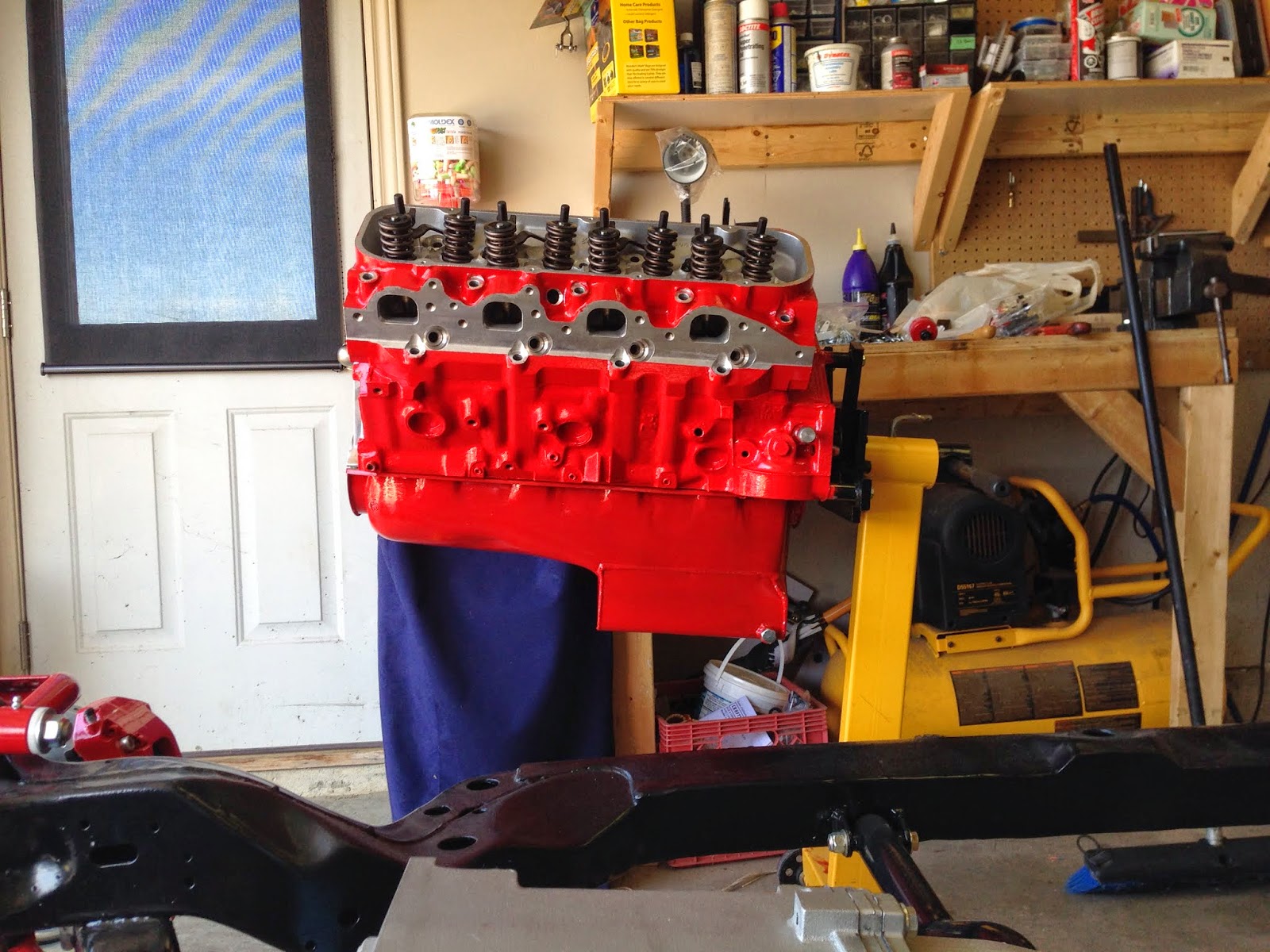
A couple years ago when I just had the engine block my plans for my chevelle were a little different. I have since changed some details of my build. I had originally painted the block Chevy orange. I have now decided I want the block to match the colour of my brakes and suspension. so after a few different paint colours I found a engine enamel in a red colour that is almost a perfect match. It ended up being POR 15 engine enamel in "Ford Red", so I officially appologize to the die hard chevy people out there for using this "Ford" colour. I have a Ford Focus and a Ford Escape out in the driveway so I have no problem with tossing a little Ford into the mix.
Here is the block before the Red


I sanded the whole block and oil pan with 300 grit sandpaper to help the new paint adhere better. After I masked off everything I didn't want to be red, I started laying down some of the new colour. I really like the POR 15 paints. I could apply with a brush and it still drys perfectly smooth, and rock hard.


Some people may ask "why did you paint your aluminum heads!" well I had seen this done while looking at other peoples builds and I liked the look..... so that's why. I'm glad I did it because, I'm very happy with how it turned out.


After I had let the parts dry I took it all back apart. Next, I waited for a nice day, took everything out into the driveway and gave it all a thorough cleaning. I used a mixture of laundry detergent and water and scrubbed everything with a variety of brushes. I used a toilet brush to scrub the cylinder walls, don't worry it was brand new, it worked well. I did all this cleaning as fast as I could while making sure to keep the block wet at all times because the freshly machined surfaces are VERY prone to rusting very fast. Once the cleaning was complete I sprayed everything down with WD-40 while also using my air compressor to blowdry the block. Once I was confident the block was dry I rubbed the cylinders down with ATF to keep them from rusting. I covered the block up with a clear garbage bag.
Here is a picture of it all cleaned and sparkling. Now I can start on the Pre-assembly measurements.

At one point I had decided that I was going to leave the building of my 454 big block build up to the machine shop that performed all the maching work to the block, but have actually decided recently that I am going to build it myself. I have wanted to do an engine build myself ever since high school automotive class where we were given the oportunity to tear apart an engine and put it back together. I keep on telling myself that you only live once so why not do the things I want to do. With the amount of research and books that I've read so far on building engines I am fairly confident at this point in doing the job myself. I will try and explain myself the best I can on here during the process.
The first thing I did before I even touched any of the engine parts was tidy up my garage. It was a disaster! so after a couple hours I had the garage to the point where it was tidier and I had a little more room to work on my benches.
A couple years ago when I just had the engine block my plans for my chevelle were a little different. I have since changed some details of my build. I had originally painted the block Chevy orange. I have now decided I want the block to match the colour of my brakes and suspension. so after a few different paint colours I found a engine enamel in a red colour that is almost a perfect match. It ended up being POR 15 engine enamel in "Ford Red", so I officially appologize to the die hard chevy people out there for using this "Ford" colour. I have a Ford Focus and a Ford Escape out in the driveway so I have no problem with tossing a little Ford into the mix.
Here is the block before the Red
I sanded the whole block and oil pan with 300 grit sandpaper to help the new paint adhere better. After I masked off everything I didn't want to be red, I started laying down some of the new colour. I really like the POR 15 paints. I could apply with a brush and it still drys perfectly smooth, and rock hard.
Some people may ask "why did you paint your aluminum heads!" well I had seen this done while looking at other peoples builds and I liked the look..... so that's why. I'm glad I did it because, I'm very happy with how it turned out.
After I had let the parts dry I took it all back apart. Next, I waited for a nice day, took everything out into the driveway and gave it all a thorough cleaning. I used a mixture of laundry detergent and water and scrubbed everything with a variety of brushes. I used a toilet brush to scrub the cylinder walls, don't worry it was brand new, it worked well. I did all this cleaning as fast as I could while making sure to keep the block wet at all times because the freshly machined surfaces are VERY prone to rusting very fast. Once the cleaning was complete I sprayed everything down with WD-40 while also using my air compressor to blowdry the block. Once I was confident the block was dry I rubbed the cylinders down with ATF to keep them from rusting. I covered the block up with a clear garbage bag.
Here is a picture of it all cleaned and sparkling. Now I can start on the Pre-assembly measurements.
Subscribe to:
Posts (Atom)