When I got my engine block I purchased a set of piston rings to go with it. They were the file to fit type, which they make larger so they can be filed to a specific gap. Which in this case I was reccomended by Keith Black (manufacturer of my pistons) 0.028" for the top ring and 0.018" for the 2nd ring. I had done the filing years ago when I originally got everything. This week I got out all the rings that were individually packaged per cylinder and I checked all the gaps to make sure I gapped them right years ago.
Below is a picture of a tool used to insert the piston rings evenly down into the cylinder squarly so the gap can be checked.
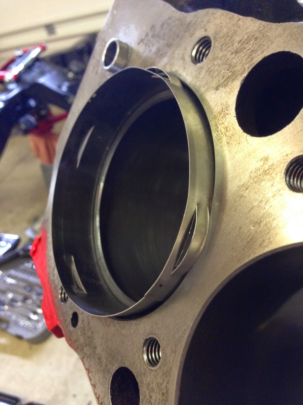
Here is a picture of the piston ring into the cylinder. The gap can be seen at the top if you look closely.

A feeler gauge is then used to check the gaps. This is then done for the 2nd ring also and for all 8 cylinders. I guess I did a good job a few years ago when gapping these rings because they all were good. I replaced them into their labeled bags and set them aside (I won't need them until final assembly).

Next, I had to measure the pistons. Every piston manufacturer has a specific spot on their pistons where they are measured. I assume this is because it is at this spot where the piston is the largest. I went onto the Keith Black website and found the installation instructions for my pistons. In these instuctions it tells me where to measure them.
Here is the link for the installation instruction sheet for my pistons for an example
https://www.uempistons.com/installation_instructions/kb_installation.pdf
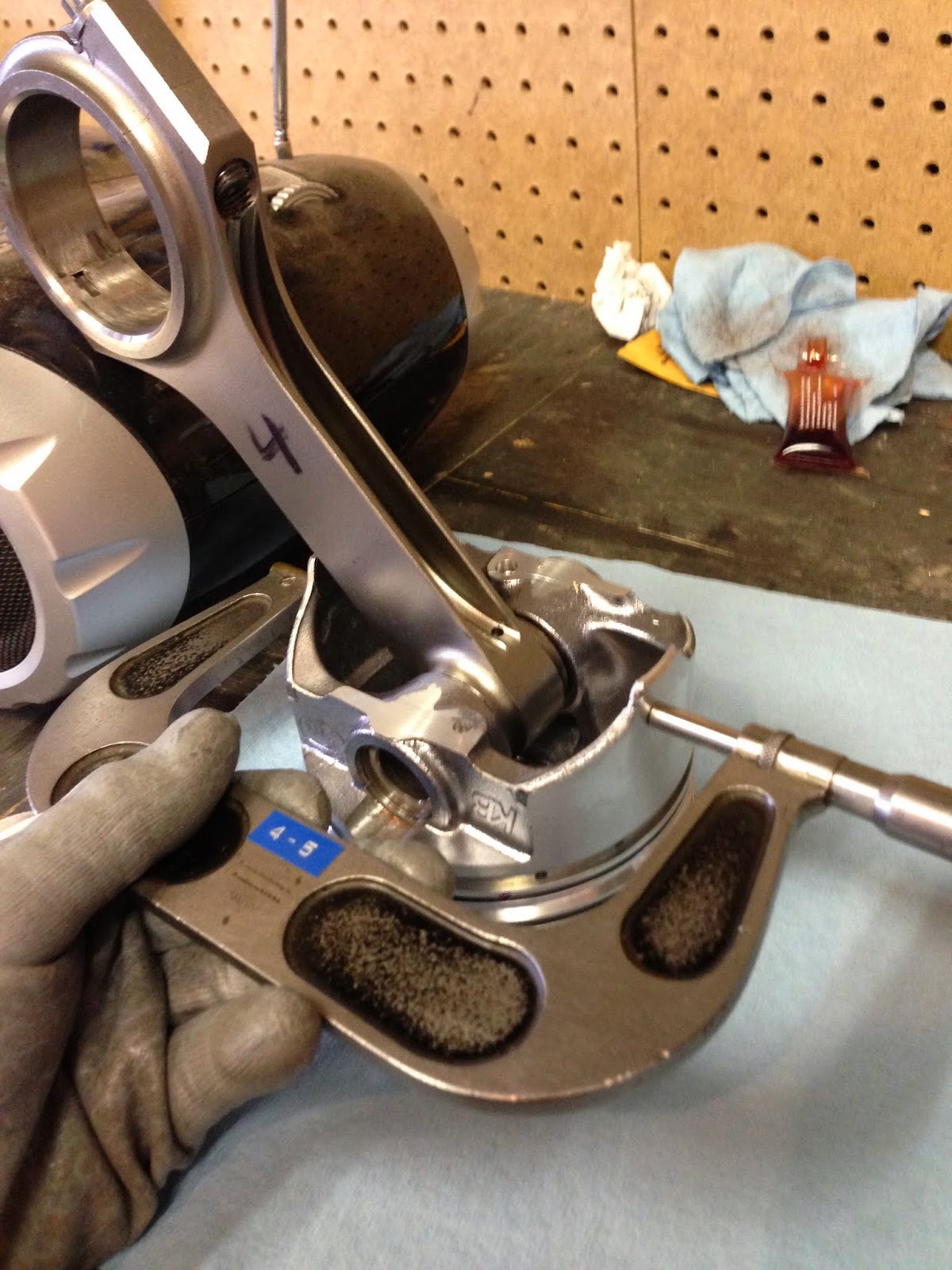
In the picture below I am measuring the #4 piston with my 4"-5" micrometer. I measured all 8 pistons this way. All of the pistons measured within .0005" of each other.
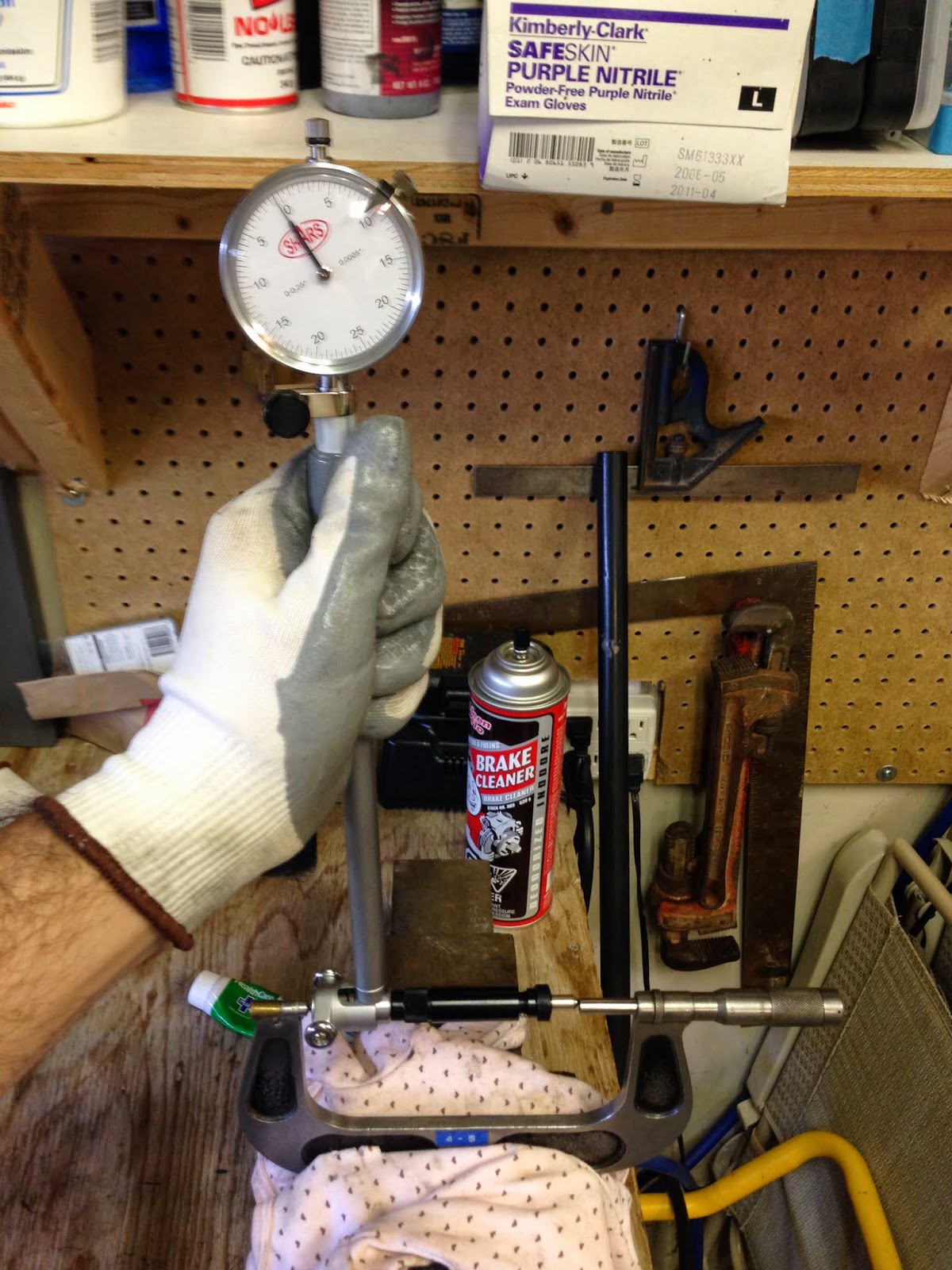
The picture below is how I set the bore gauge to zero using my micrometer set to each specific piston size. It's hard to take a picture of this, but I tried my best.

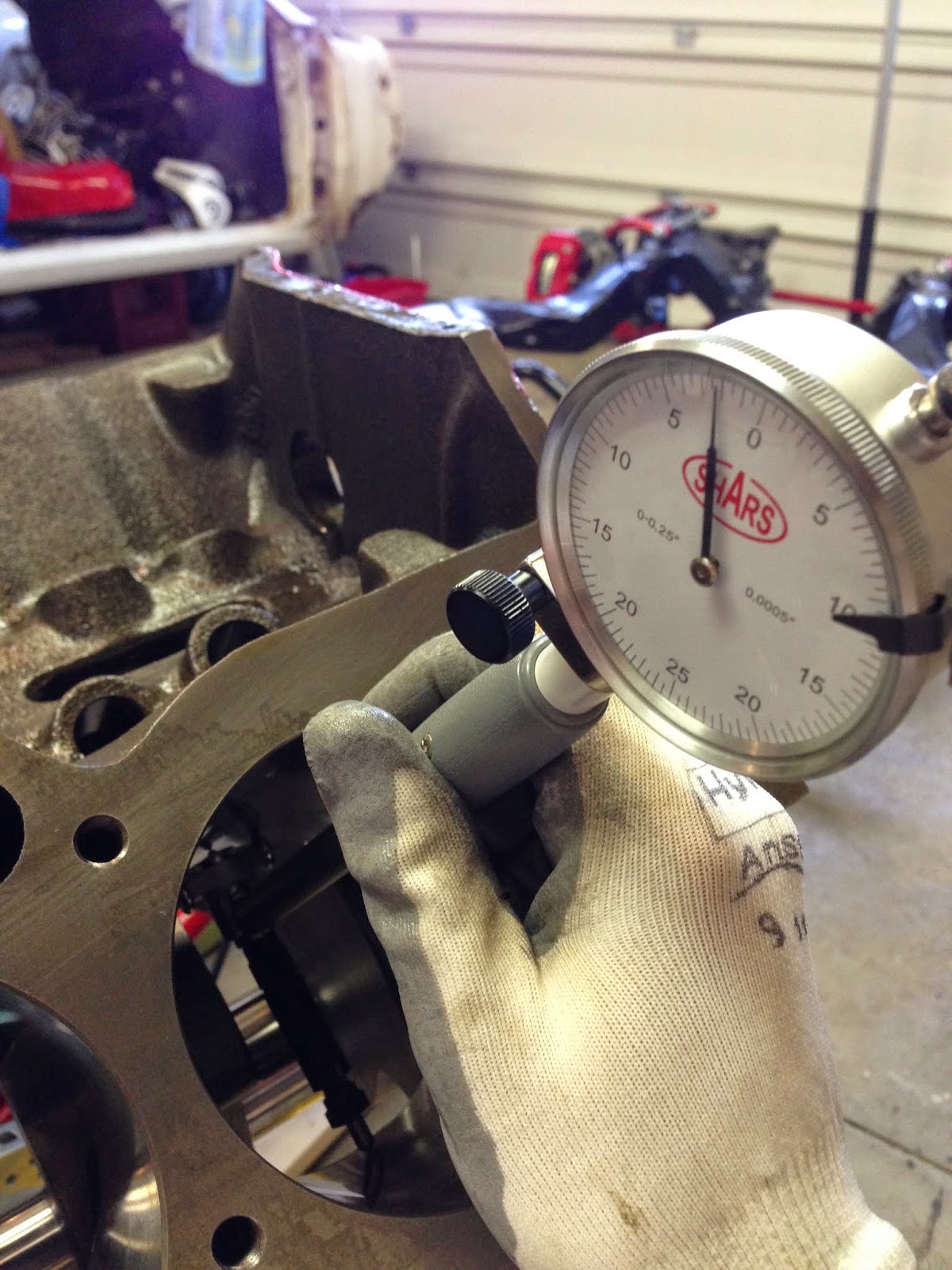
I checked each cylinder horizontally and vertically to double check the machining work and make sure the cylinders aren't out of round.

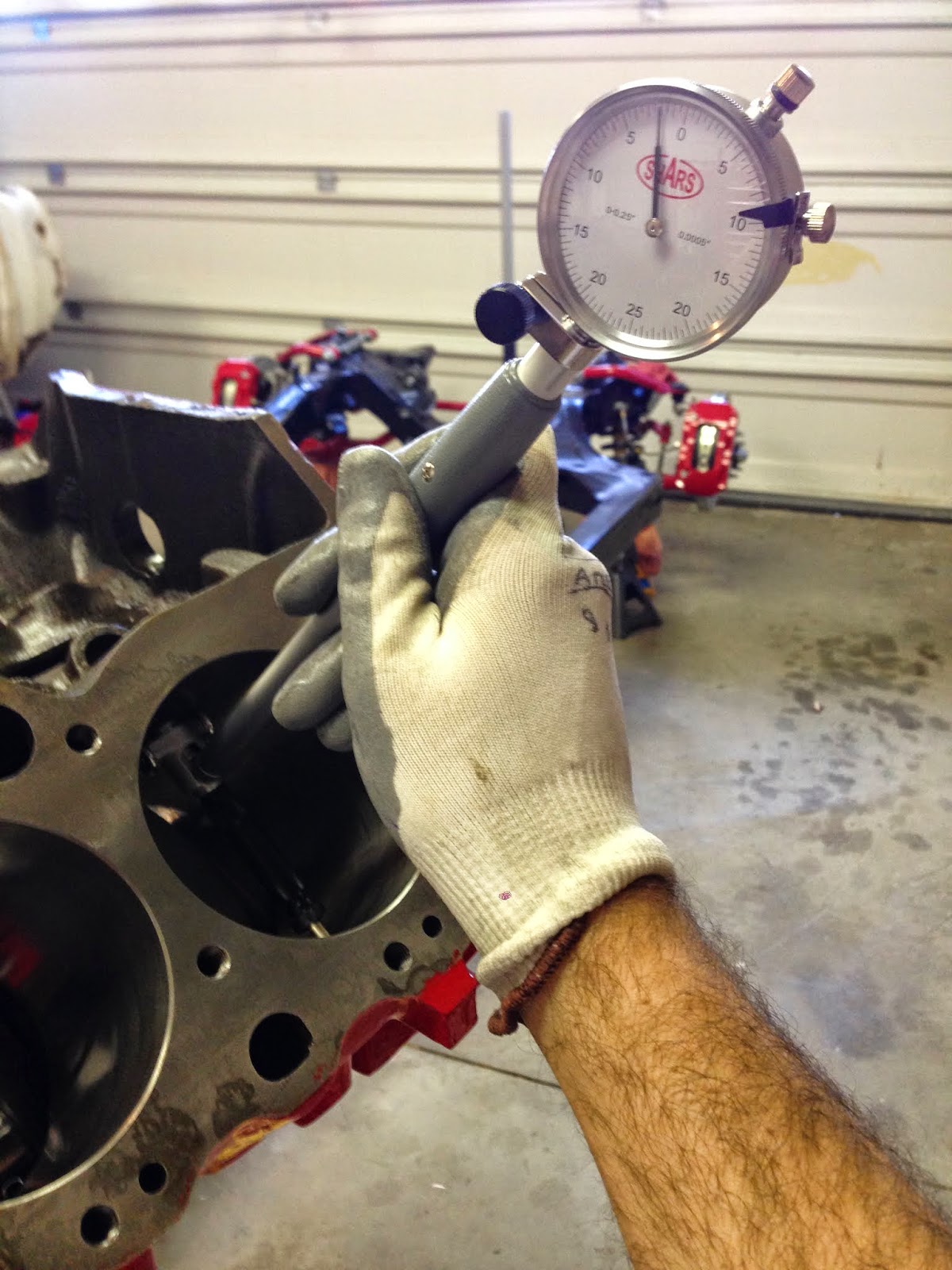
The picture below is showing an example of one of the cylinder piston to wall clearances I got. Each line is 0.0005". So this is reading .0020" clearance.
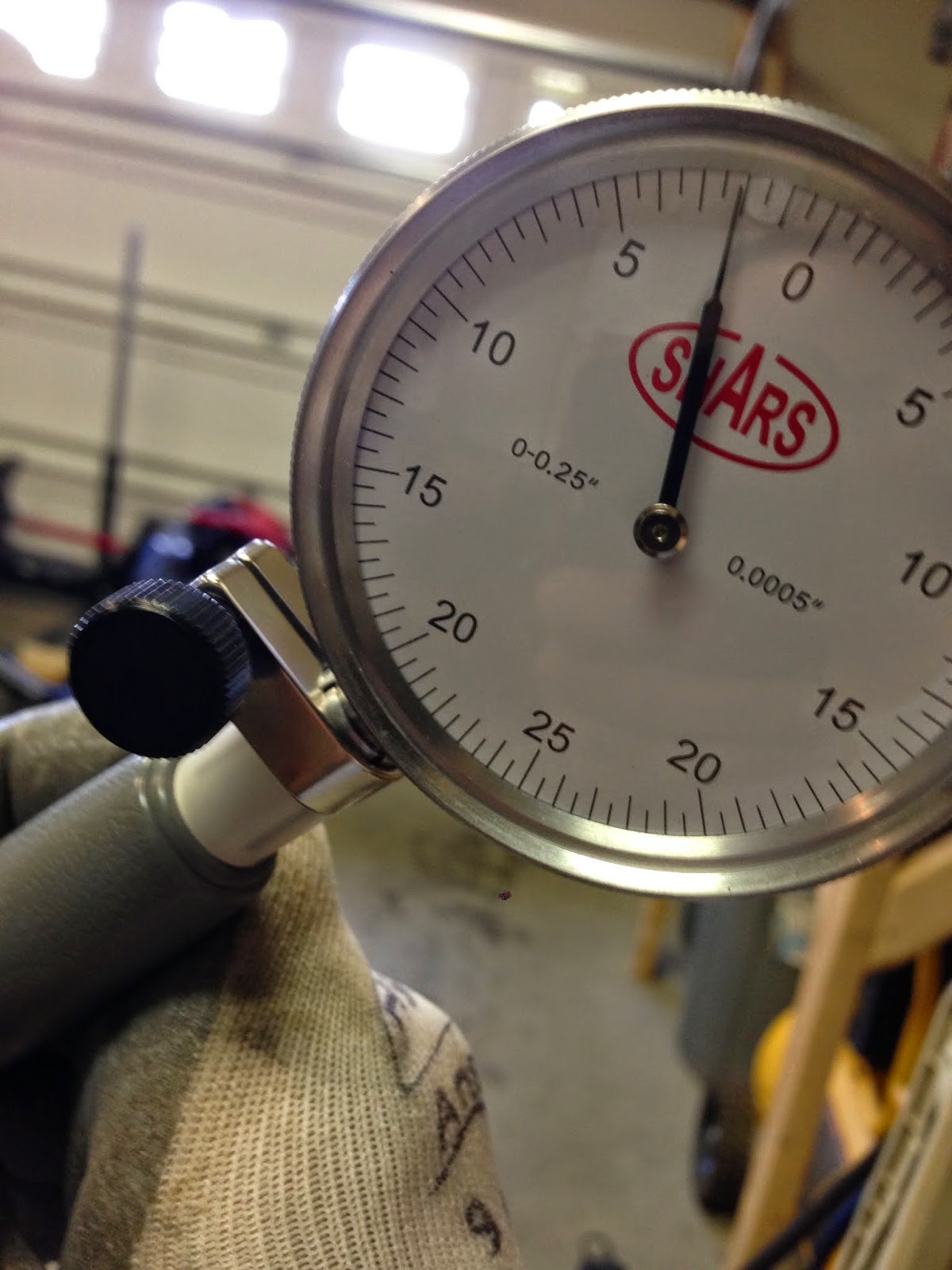
All the piston to wall clearances checked out ok from .0020" to .0025". I once again looked at the piston installation sheet that I printed off from the KB website. These clearances were exactly what they suggested for a street performance engine.
Here is my handy white board again with all my measurements recorded.
