Friday, December 5, 2014

Engine Build Pre-Assembly (Oil Pump Fit and Clearance to Pan)


I am almost coming to the end of the pre-assembly stage of my engine build, there are just a few other things to do.  With both heads on the block tightened down just snug (not torgued)  I installed the intake manifold with just 4 bolts to make sure it lined up on the heads ok.
 

I'm really glad I went with the black powdercoated version on the intake manifold.  I really like the look of the black on red, and it will go well with the black on red look of my chevelle when it's done.


I then test fitted the distributor in the block and tightened it down with it's hold down clamp, because next I will be turning the engine upside down.


With the engine upside down I put the oil pump driveshaft down into it's hole in the block.


The picture below shows the oil pump driveshaft in the block.  Also I installed the oil pump stud in the block.


I then tightened the oil pump onto it's stud.


The oil pump driveshaft play is then measured.  To do this, using my pinky finger I slid the driveshaft as far up as it would go.   I then drew a line on the oil pump, where the two met.  I then pushed the driveshaft down as far as it would go and made another line.


Below are the two lines that were made on the oil pump shaft.  This indicates that there is some endplay with the driveshaft, which is good.


I next installed the oil pump pickup into it's hole in the oil pump.  It is a press fit and had to be tapped down into the hole using a punch.
  

The oil pump and pickup that came in my kit had a locating tab on the pickup that set the pickup to it's desired depth within the kit's oil pan.  I will be verifying the clearance between the pan and pickup just to be sure.


The bolt in the oil pump kit is removed and then reinstalled over the pickup locating tab.


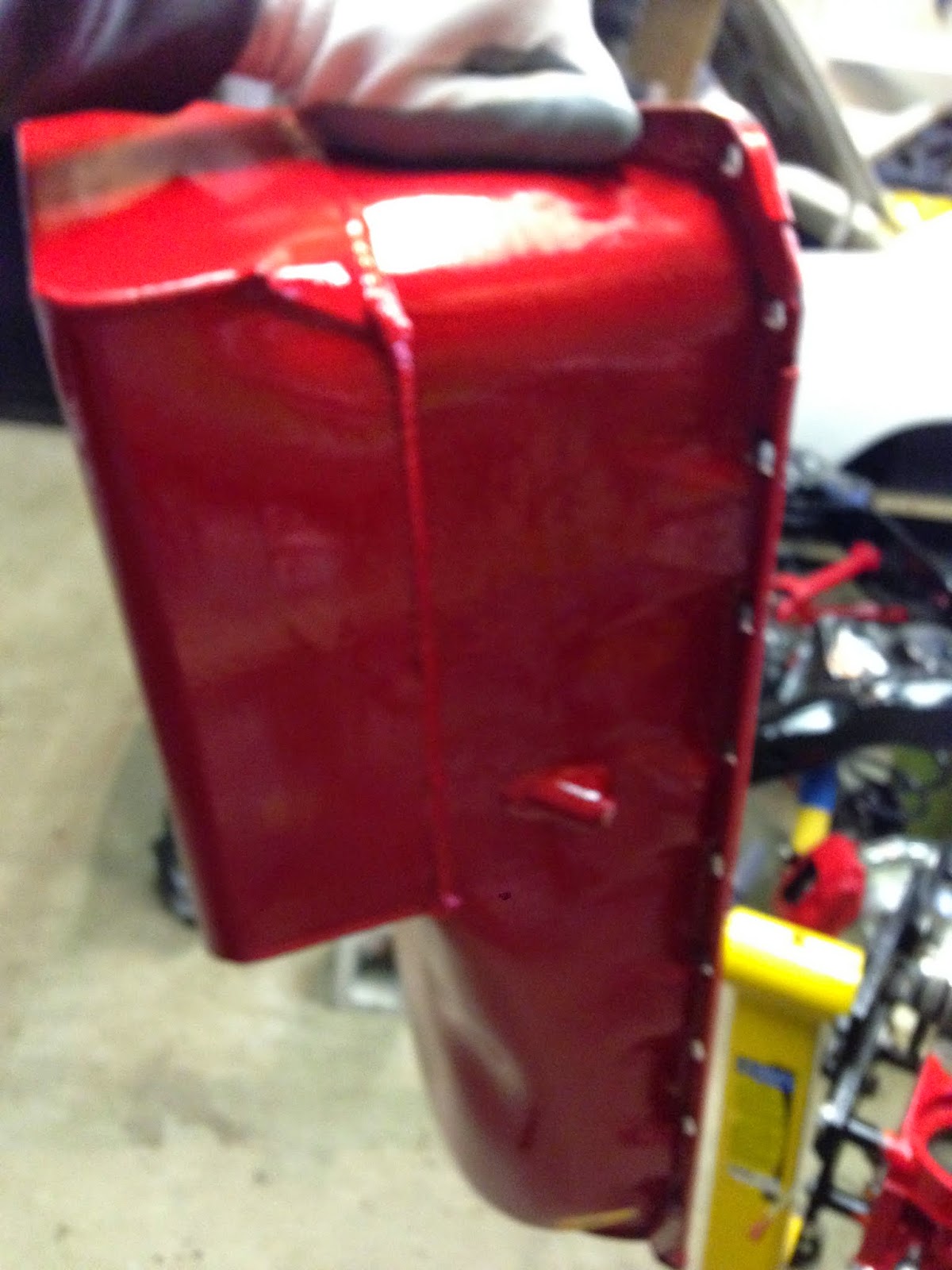
Here is the oil pan


To check the clearance between the pan and the oil pickup, I once again pulled out some modeling clay.  I placed a blob on top of the pickup.


The pan was then placed onto the block, which in turn squished the clay to the clearance.  I then removed the pan again and using my calipers measured the thickness of the clay.  I forgot to take a picture of this, but I measured the clearance to a little bit less then 3/8" which is good.


All my engine pre-assembly checks have now been completed.  I am happy with all my measurements that I have taken.  I now will start to dissassemble the engine in preparation for final assembly.

Thursday, December 4, 2014

Engine Build Pre-Assembly (Piston to Valve Clearance)

 
Piston to valve clearance is a very important measurement that must be performed in any engine build.  In all my research I came across two different methods of doing this.  The first is using a dial gauge set up on the valve spring retainer and checking at different intervals of crankshaft revolution how far the valve can be pushed down before contacting the piston (more on this farther down).  The other method of checking is using clay, which I will explain.  I did both checks, this is my first engine build so I figure better safe than sorry.
 
Here is the dial gauge set up on the valve spring retainer.


The degree wheel is used again for this check.  I brought the piston to 20 degrees before top dead centre (BTDC) as my starting point.


I then pushed down on the lifter slowly watching the dial gauge until I felt the valve contact the piston.  I recorded the reading from the gauge at this point.  I then moved the crankshaft in the normal rotation (clockwise) to different degrees in the crankshaft rotation and did the same thing.

After I did the measurements for the intake valve I moved the setup over to the exhaust valve and did the same thing.


Below are the recordings that I got at each interval.  It looks like the closest clearances seem to be about 8-10 degrees after top dead centre on the intake valve and 6-8 degrees before top dead centre.  Minimum clearance on the intake valve should be 0.080" or more and for the exhaust side 0.100" or more.  My numbers are well within safe limits.


Next I decided to see what clearance numbers I get using the clay method.  I won't be needing to have the light weight checking springs on the number 1 valves anymore so I first swapped the regular springs back into the head.

Below I have my valve spring compressor set up.


The valve is compressed to insert the two valve retainers in


Below are the two valve spring retainers


Valve spring installed


To perform the clay method of checking piston to valve clearance the head gasket needs to be used also to get a accurate value. 


A chunk of modeling clay was placed on the #1 piston, enough to cover the whole span of the piston where the intake and exhaust valves are.


The cylinder head was then placed on the block and just snugged down. 


The valve train for the #1 cylinder are setup again.   Once again using the lifters that I made into solid lifters.  The engine was then turned over a few times, enough that the intake and exhaust valve open a couple times.


Everything is then taken off again.  Below the intake and exhaust valve indentations in the clay can be seen.


Carefully using an x-acto knife I cut each indentation in half.  I then used my calipers to measure each indentation at it's thinest points.