Thursday, December 4, 2014

Engine Build Pre-Assembly (Piston to Valve Clearance)

 
Piston to valve clearance is a very important measurement that must be performed in any engine build.  In all my research I came across two different methods of doing this.  The first is using a dial gauge set up on the valve spring retainer and checking at different intervals of crankshaft revolution how far the valve can be pushed down before contacting the piston (more on this farther down).  The other method of checking is using clay, which I will explain.  I did both checks, this is my first engine build so I figure better safe than sorry.
 
Here is the dial gauge set up on the valve spring retainer.


The degree wheel is used again for this check.  I brought the piston to 20 degrees before top dead centre (BTDC) as my starting point.


I then pushed down on the lifter slowly watching the dial gauge until I felt the valve contact the piston.  I recorded the reading from the gauge at this point.  I then moved the crankshaft in the normal rotation (clockwise) to different degrees in the crankshaft rotation and did the same thing.

After I did the measurements for the intake valve I moved the setup over to the exhaust valve and did the same thing.


Below are the recordings that I got at each interval.  It looks like the closest clearances seem to be about 8-10 degrees after top dead centre on the intake valve and 6-8 degrees before top dead centre.  Minimum clearance on the intake valve should be 0.080" or more and for the exhaust side 0.100" or more.  My numbers are well within safe limits.


Next I decided to see what clearance numbers I get using the clay method.  I won't be needing to have the light weight checking springs on the number 1 valves anymore so I first swapped the regular springs back into the head.

Below I have my valve spring compressor set up.


The valve is compressed to insert the two valve retainers in


Below are the two valve spring retainers


Valve spring installed


To perform the clay method of checking piston to valve clearance the head gasket needs to be used also to get a accurate value. 


A chunk of modeling clay was placed on the #1 piston, enough to cover the whole span of the piston where the intake and exhaust valves are.


The cylinder head was then placed on the block and just snugged down. 


The valve train for the #1 cylinder are setup again.   Once again using the lifters that I made into solid lifters.  The engine was then turned over a few times, enough that the intake and exhaust valve open a couple times.


Everything is then taken off again.  Below the intake and exhaust valve indentations in the clay can be seen.


Carefully using an x-acto knife I cut each indentation in half.  I then used my calipers to measure each indentation at it's thinest points. 


Sunday, November 9, 2014

Sidetracked


The engine build has been put on hold for the time being.   Winter is coming here in Canada and I'm trying to get my garage in order before the snow hits.  I thought I'd just let everyone that's following my blog know what I've been up to. 


My garage isn't heated or insulated.  After last years winter that seen temperatures dropping close to  -40 I decided it needs to be heated if I want to get anything accomplished.  I went over across the border to Menards and got a good deal on some R38 insulation and used this to insulate the ceiling.    I also picked up a 50k btu Mr. Heater at Lowes.  Hopefully it does the job. 

Here is a picture of it hung on the ceiling.  I just have to get the gas and electrical hooked up and the exhaust.


I also got an early christmas present.  A new tool chest.  I've been looking for awhile for a bigger tool chest to accomodate my ever growing tool collection.  So I finally broke down and went and got the biggest chest combo Canadian Tire offered in their store.   If it doesn't fit all my tools, then I think I need to get rid of some.

With alot of my garage time lately I've been transferring my tools into the new chest.


I'm still going to use my old tool boxes.  I think I'm going to use them to hold chevelle/engine parts and stuff like that.


I'm hoping with all the newly aquired storage I can cut down on the clutter, which can be seen on my tool bench in the above picture.   I know it's bad.....haha

I've also been using some of my time to make repairs on our family vehicles and getting our house ready for the winter. 

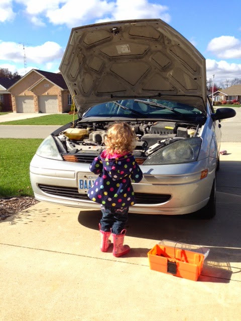
Here's my helper mechanic making some repairs to my Focus. 


Anyways, that's what I've been up to lately.  I will get back to the engine build soon.  If anyone has any suggestions on some tool chest organization tips I would gladly take some.  Just comment on this post.

Tuesday, September 30, 2014

Engine Build Pre-Assembly (Pushrods)


In my last post I had ordered my pushrods.  I actually lucked out and Comp Cams offers a kit for my exact setup with 7.725" intake pushrods and 8.684" exhaust pushrods.  So I placed my order through Summit Racing.  I have been getting most of my stuff through Summit because I find their service excellent.  Most everything I have purchased from there is lower price then anywhere I have found and they ship very fast.  I placed my order for the pushrods and it was shipped an hour later.  I got the pushrods the next day.

The kit I got are the 3/8" thick pushrods which is what I need because that is the size of the pushrod guideplates on my cylinder heads.  The guideplates do exactly what the name suggests.  They hold the pushrods and actually hold the rockerarms from walking around side to side when the engine is running. 


Next thing to do will be to perform the same checks as in my last post, but using the actual pushrods in place of the checking pushrods to see if I can get the same wear patterns on the valve tips.

In the picture below you can see the exhaust pushrod sitting nicely in it's guideplate.


Here is the wear pattern I got with the new pushrods.  If you notice, the wear pattern is slightly on the outboard side of the valve tip.  This is because I am still using the solid lifters in place of the hydraulic lifters for the checks.  Once I put the engine together for the final time using the hydraulic lifters I will be putting a preload on the lifter.  This basically means I will be tightening the rocker arm a small specific amount more which will push the lifter plunger down into the lifter body a small amount.  Once I put that required preload on these lifters that will bring the rocker arm travel exactly where I want it.


Here is a good picture showing the combustion chambers on one of the cylinder heads.  Look at the size of those valves!.... it's not going to be fuel efficient, that's for sure.


I put the other cylinder head on.


I set up the #2 cylinder valvetrain.  I'm going to see what the wear pattern looks like on this side, just to double check.  I didn't have to use the checking springs this time because I was using the actual pushrods and didn't have to worry about the spring pressure bending them like the pushrod checkers.


Wear pattern looks good on this side too.  Once again, a tiny bit on the outside tip of the valve.  But once the lifter preload is set this will be right in the middle.  The preload will be somewhere in the ball park of 0.030"-0.060".
 

Next thing I did today was set up my dial indicator on the top of the valve retainer.  I'm going to verify that my rocker arm ratio is actually 1.7.  This means that the rocker arm actually opens the valves 1.7 times the lift of the lifter.   During this check I'm also going to check the valve spring retainer to the valve seal clearance.

The dial indicator is set up on the valve spring retainer and set to zero.


The engine is turned over until max lift is achieved (the dial indicator stops and reverses direction at max lift).  This number is recorded.  At max lift I took a screw driver and pushed the spring down to take a look and verify the retainer to valve seal clearance.  I did not need to use a feeler gauge here, I could tell that there was plenty of clearance here.  It needed to be more then 0.070".

The picture below is kind of hard to actually see, but I was checking the distance between the top spring retainer to the valve seal on the bottom inside the spring.


Checking the intake side also


Here is max lift on the intake valve.  It read 0.550" lift.


For the exhaust valve I got a max lift of 0.566".  So in one of my previous posts I measured the lift at the actual lifters which was 0.319" on the intake and 0.330" on the exhaust.   If you take each of those and times them by the rocker ratio that gives my a theoretical lift of 0.542" (intake) and 0.561" (exhaust).   So my actual lift results are very close to theoretical lifts, only off by .008" (intake) and 0.005"(exhaust).  I will chalk that up to accuracy errors on the instruments.

I'm getting pretty close to being done the pre-assembly checks, just a few more things to do.

Friday, September 26, 2014

Engine Build Pre-Assembly (pushrod length measurement)

 
Next up on the pre-assembly checks to do list is to figure out what size pushrods I will be needing.  To do this I will be bolting the cylinder head on, torquing it to spec, and then setting up the valvetrain for the #1 cylinder.
 
Below is the head gasket installed
 

Torquing the head bolts down in the proper sequence to 75 ft/lbs


I will be using my solid lifters that I explained in my last blog entry.  Here they are in the #1 intake and exhaust lifter bores.


To determine the pushrod length pushrod checkers are used.  They are basically a pushrod that has a threaded section so the length can be increased or decreased in size.  Because big block chevrolet motors have 2 different size pushrods for the intake and exhaust, I had to get 2 different pushrod checkers.  One that measures 7.5" to 8.7" used to measure the intake side and one that measures 8.5" to 9.8" used to measure the exhaust side. 
 

Before I did this I had gone on to Comp Cams website and was looking at the sizes of pushrods they offer.  I noticed they had a kit for a 454 Engine with their retrofit cam.  I thought I would set my checkers to their sizes and see how they fit. 

Next to do was to set the rocker arm up.  To do these checks I had to swap the normal valve springs for light checking springs.  If the regular springs were used with the pushrod checkers there is enough pressure that they could be bent.

The picture below shows where the rocker arm would sit if the pushrod was too short.  The roller is sitting too far inboard on the valve stem.

 
As the pushrod is lenghthened the roller now sits more in the middle of the valve stem.
 

In order to make sure the pushrods are the right length I needed to see where the roller tip on the rocker is actually riding during opening and closing.  To do this I coloured the top of the valve stem with a sharpie before putting the rocker on.  As I spin the engine over and the rocker, pushrod checker (set to length) and lifter open and close the valves the rocker tip will wear a pattern in the marker.

In the picture below is example of where the pattern should be.  I lucked out and the Comp Cams pushrod set that they have is a perfect fit and provided good results


Pushrod checker set to length


Setting the pushrod checker to the desired lengths


Below, I am installing the rocker arm on the valve at "zero lash".  This means that with the lifter on the base of the cam lobe (lowest point) the locking nut on the rocker stud is tightened down just until all slack is taken out of the pushrod, no more.  When I go to install the pushrods and rockers on final assembly I will be taking them to zero lash and then turning the locking nut another half turn, which puts a "preload" on the hydraulic lifter.  I will explain more on this when doing the final assembly.


This picture below shows a wear pattern too close to the outboard side of the valve.  In this case the pushrod would need to be shorter.


When I was done and I was happy with the wear patterns on both the intake and exhaust valves I ended up ordering the Comp Cams push rod set with 7.725" intake pushrods and 8.684" exhaust pushrods.  Once I get the pushrods I will do this test once more to double check correct length.

Sunday, September 21, 2014

Engine Build Pre-Assembly (making a hydraulic lifter a solid lifter)

Hydraulic lifters in an engine are pumped up with pressurized oil, in the lifter body, when the engine is running.  This pressurized oil fills the lifter body and holds the inner plunger up against the pressure of the pushrod while opening and closing the cylinder valves.

During my engine pre-assembly I have to perform some measurements obviously without the engine running providing the lifters with the pressurized oil to the lifters.  If I were to do this with my hydraulic lifters the way they are, the inner plungers would collapse, providing errors in the measurements.  So in order to perform these measurements I need to either buy a solid lifter the same size as my lifters or take apart a pair of my lifters and make them into a solid lifters so the inner plunger won't collapse while making measurements.  I had talked to Comp Cams tech support asking them about getting a pair of solid lifters with the same measurements as my hydraulic lifters.  They told me that they do not have any, so the choice was made for me.  I was forced to dissassemble a pair of my lifters and make them into a pair of solid lifters.


First I had to remove a retaining clip that holds the plunger assembly inside the lifter.  It was actually a smaller version of the spiral locks that I used on my pistons.   So because I had the experience from using them on the pistons I removed them fairly easy.  I wish I had a magnifing glass though because my eyes are gettting worse as the years go on......


The cup was removed along with a spacer


I found I had to remove the tie-bar that holds the lifter pair together.  The tie-bar rivet was preventing the plunger from sliding out.  Unfortunately they were pressed in so had to be driven out with a punch and hammer.  After doing this I don't think I will be reusing this lifter pair in the final assembly, I will just purchase a new pair (I checked and made sure I could buy a pair first, in case I had to).  Cheap insurance I suppose, instead of trying to return them to the hydraulic set.  I will keep them in my tool box, who knows maybe I'll build another engine.


Below the picture shows all the parts of the lifter laid out.  From right to left: spiral lock, pushrod cup, spacer, plunger, spring and lifter.  The tie bar is above all the pieces.


Next I had to fill the space inside the lifter body that would have normally been where the spring sits.  I got some small washers and nuts to do the job.  This actually took a little while to figure out how many washers I needed to bring the plunger to the same spot (flush with the spiral lock groove in the lifter body).  With one nut and one washer I was able to have the plunger in the exact same placement in the lifter as when the spring was in.


The picture below is a view looking into the lifter with the nut and washer inside


Installing the plunger back into the lifter


Installing the cup and spacer back into the lifter


Installing the spiral lock back into the lifter to hold it all in


And that's it, a hydraulic lifter made into a solid lifter for measurment purposes.  I did the same with the other lifter.