Friday, November 20, 2015

Engine Build- UH OH!


After writing my last post I ran into a MAJOR problem, by major I mean one of the worst things that could of happen other than blowing the thing up, at least that's what I initially thought.  After the initial break in I ran it a couple more times and each time I kept noticing a small coolant drip on the floor.  I took a couple bolts off the block and sealed them thinking that this was the source but it never stopped.  Well after awhile I seen where the drip was coming from, BEHIND the engine block paint!  I grabbed a screwdriver and chipped away the paint and there it was a crack in the water jacket on the block.


Small crack can be seen after I chipped the paint away. 


After I was done swearing, and throwing things around the garage I calmed down and thought about my options.  Option 1, scrap the block and get a new one.  New was going to be around $2000, another used block was going to be around $1200 by the time I had it re-machined.  This option would require me to completely disassemble the engine and start from scratch.   Option 2,  I buy some of these "miracle" crack repairs that you put into the rad and circulate through the coolant.   Option 3, try and find a good enough welder to weld cast.  Option 4, a procedure called "cold metal stitching" where a series of threaded overlapping plugs are installed along the crack which fuses all new material where the crack was originally. 


luckily the machine shop that had done all my original machine work to the block said they could do the stitching for me.  I decided to go this route because I didn't want to start from scratch and I didn't want the "patch" job of using the rad/coolant fixes.    So I had to drain all the coolant and oil and take the carb off for them to do the work.  I then loaded it up and dropped it off at the shop.  After a couple weeks I picked it back up and it looked great.  The real test was going to be running it again.  They were confident.


This is the full crack that can be seen after magna-fluxing


It was a lot bigger than I expected it to be


Here is the finished job, if you look closely you can see the small plugs along the crack


I just need to repaint it now


Loaded up, on way home.


I took it home and hooked it all back up to my engine stand, and fired it up.  I put some Irontite All Weather Seal (shop recommended this as a insurance).  It is a sealant that is put in with the coolant that searches out and leaks any seals them up.  Well after running for a good 40 min or so of hard revving and idling,  I can report NO LEAKS.  Now I hope it holds up over time.


I learned one big lesson.  When using a used engine block for a build, have it checked for cracks.  I had painted the block before bringing it in to initially have it machined, I guess I shouldn't have done this because they can't magna-flux the block over the paint.  I didn't know this.  I also think that they should have suggested that I strip the paint off and have it done.  I think there were faults on both sides.  I know for next time now.  lesson learned.


Thursday, September 3, 2015

Engine Build - Initial Break In Run


During these last few months I have been able to finish my first engine build, build a engine test run stand, and I fired up the engine for it's initial break in run.    I also made a time lapse video of the final assembly of the engine.   The time lapse can be seen in my previous post.  The video is a combination of over 12, 000 photos that I took during the assembly.  I had setup our camera on a tripod with a timer and had it take a picture every 3 seconds.  I then took all those photos and using a program they were put together to make a video.

When I finished the engine build I decided I wanted to build a engine run stand for two reasons.  First reason is I wanted to be able to break the motor in with easy access to the engine in case anything needed repair before putting into the Chevelle.  The second reason I wanted a stand was because I don't think this will be my last engine build, and it would be nice to have one if I ever decided to do another engine.

I made the stand out of wood because my carpentry skills are a lot better than my welding skills and I also had a lot of lumber lying around the garage.


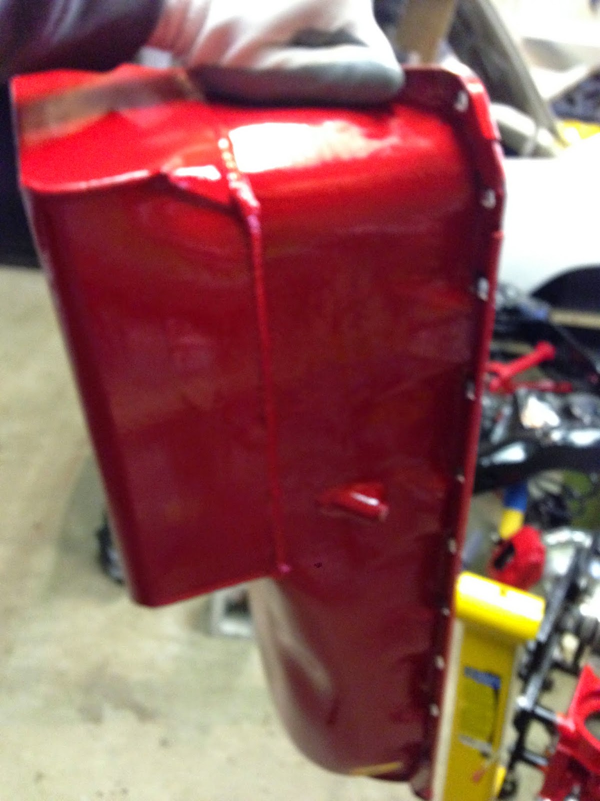
I mounted the old rad that I had from the Chevelle.  This is when I ran into my first problem.  After I had everything hooked up and ready.  I started filling the rad with coolant.   The rad had been sitting out in my shed for a few years through some pretty nasty winters so it must have cracked the coil somewhere inside, because coolant started pouring out the bottom of the rad.  It was junk.  So I decided this was my opportunity to get the rad setup I will be using for the Chevelle and get a chance to test it out on the stand also. 

I ended up going with a Griffin aluminum rad with dual 12" Spal fans.  I went with this setup because of a few reasons.  They had great reviews, their customer service with me was excellent and the setup was significantly lower in cost compared to similar big name setups.

It was a big box, so I needed some moving help as can be seen below.


She also runs my quality control inspection department seen below inspecting the fins.


Dual Spal Fans, The setup came with all wiring and controls needed for easy install.


Installed on the run stand


Here are a couple pictures of the complete stand with the engine wired and ready to run.


Before I started the engine for the first time I made sure to set up the engine to fire as soon as I started cranking it over.  There were a few things I did to ensure this.  First I set the #1 cylinder at approx. 12 degrees before top dead centre on the compression stroke.  I had the spark plug removed from the #1 Cylinder.  I rotated the engine over and at the same time had a finger over the spark plug hole.  When the piston is on its way up on the compression stroke the compression can be felt on your finger, blowing air out the hole.  I then brought the crankshaft up to the 12 degree before top dead centre mark on the harmonic damper.

The next thing I did was setup the distributor so that it was as close to firing the #1 cylinder spark plug at the same moment.  To do this I wired the distributor cap up in the correct firing order (I triple checked that I had the wires routed correctly).  I then lifted the rotor cap off, and set the distributor body so that the rotor was lined up to where the #1 wire was on the cap.    By doing these first steps I was ensuring that the initial timing was close enough to get the engine running quickly.

One other thing I did was fill the carb up with fuel.  To do this for me was easy because I am using an electric fuel pump.  All I had to do was hook my fuel lines up,  turn power on to the pump and ran if for about 5-10 seconds.  What this did was fill the carb fuel bowls up with fresh fuel so that when the engine was turned over it got fuel going in right away. 

The last thing I did was pre-oil the engine.  I have a tool that is modeled after the bottom section of a distributor so you can hook it up to the oil pump drive in the block.  I slid it into the block onto the oil pump drive and then using my battery drill spun it for about 5 minutes making sure I was getting some pressure reading on the oil pressure gauge I had hooked up.

I was now ready to fire this engine up.  I must have set the engine up correctly because it fired right up.  I was actually surprised at how fast it did fire up, I was expecting a bit of cranking before it happened. 

The video below is the 1st start. 


Here is the 2nd attempt


The above videos you can see it is running pretty rough.  It wasn't firing on all cylinders and I traced it back to a bad battery.  I was able to get my hands on a battery booster and once it was hooked up to the battery the engine ran great and I was able to set the timing.  The video below is with the booster hooked up.  You can hear it running alot better.


After I had run the motor a couple times and gave it a good run in, I let the engine cool down and drained the oil and took the oil filter off.  This is done so I can look at the oil and make sure no metal was found in it.    I even used a strainer and filtered the oil and the only material I found in the oil was a little bit of fuzzy lint material, I think that this was probably a bit of lint from the shop towels I used during assembly.


At this time I also took the tappet covers off to inspect the valve train and re-tourque the head bolts.    When I had the tappet covers off, I found an issue.  I was looking at the rocker arms and I noticed that some of the roller tips weren't centered on the valve stems.  The rocker arm tips are supposed to be centered on the valve tips and this is accomplished with the push rod guide plates.  After some research I found that there have been some issues with the guide plates that come on the Edelbrock cylinder heads.

To fix this issue I ordered some Comp Cams guide plates and installed them.  This fixed the problem and the tips were centered properly in the valve stems.
  
Below is a picture of the new guide plates installed.


Below is a picture of the edelbrock guide plates


I am extremely happy with how everything turned out with my first engine build,  I've learned so much already about engine building and would like to do another engine (maybe after the Chevelle is done).  This has been my favorite part of my Chevelle build so far.


Friday, August 21, 2015

Engine Build- Final Build Time Lapse Video

Here is a time lapse video I made of the final build of the engine.   My next post I will describe in detail how everything went on the intial break in start.  For now here is the video

https://www.youtube.com/watch?v=U47F7jKdHmc


Monday, May 18, 2015

Engine Build Final Assembly

I haven't posted on here in a awhile, so I thought I'd throw out a post just to give those following my blog a little update.  It's not that I haven't been doing any work,  I actually have been out in the garage a lot lately working on the final assembly of the 454.  I am just going about the documenting of this stage a different way.  I am putting together a time-lapse photography video of the complete final build.    I won't be posting it until it is complete, so stay tuned.   But for now here is a couple pictures of where I'm at now.


Sunday, January 25, 2015

Sidetracked Continued


Now that it is getting a lot colder here, I got my garage heater hooked up.  It is pretty much done, I just have to finish a few cosmetic things (paint gas line, install faceplates on outside and inside where the exhaust line goes through the walls, etc.).  It works great!  It's a lot nicer working out in the garage when it's not -20 in there.


 '
I was also done with all my pre-assembly checks for the engine.  So in my spare time I've been disassembling it and storing the parts in preparation for the final block cleaning and assembly. 

Here is my expert technician lending me a hand


Before the final block cleaning and assembly, I took this time to install a lifter valley screen kit that I purchased from Milodon.  This kit is installed as insurance in case any valve train failures were ever to occur.  The screens that are epoxied to the oil drain down holes would catch any small pieces preventing damage to the lower rotating assembly.  It's not that I don't trust my work, I just thought for $30 why not?  Looking back now I probably could have made the screens myself and just bought some epoxy, instead of buying the kit.


Below is a picture of the screens epoxied in.  Not the prettiest work, but this won't be seen.


In the kit there is also a screen to install in the opening where the oil goes into the timing chain area.  This screen was hammered in place using a hammer and socket.


I've also picked up a new water pump.  I found it on Rockauto.com for $15.  It's for a 1980 Suburban truck.  It should do the job, if not I'm only out $15.


I also had a meeting with the guy who is going to be doing all the body and paint work for the Chevelle.  We set a tentative date for next January.  I can't wait!

That is it for now.  I think next job for me will be to start installing brake lines and fuel lines on the Chevelle's frame.  I am going to start final engine assembly when it gets a little nicer outside so I can roll it out into the driveway and wash it.


Friday, December 5, 2014

Engine Build Pre-Assembly (Oil Pump Fit and Clearance to Pan)


I am almost coming to the end of the pre-assembly stage of my engine build, there are just a few other things to do.  With both heads on the block tightened down just snug (not torgued)  I installed the intake manifold with just 4 bolts to make sure it lined up on the heads ok.
 

I'm really glad I went with the black powdercoated version on the intake manifold.  I really like the look of the black on red, and it will go well with the black on red look of my chevelle when it's done.


I then test fitted the distributor in the block and tightened it down with it's hold down clamp, because next I will be turning the engine upside down.


With the engine upside down I put the oil pump driveshaft down into it's hole in the block.


The picture below shows the oil pump driveshaft in the block.  Also I installed the oil pump stud in the block.


I then tightened the oil pump onto it's stud.


The oil pump driveshaft play is then measured.  To do this, using my pinky finger I slid the driveshaft as far up as it would go.   I then drew a line on the oil pump, where the two met.  I then pushed the driveshaft down as far as it would go and made another line.


Below are the two lines that were made on the oil pump shaft.  This indicates that there is some endplay with the driveshaft, which is good.


I next installed the oil pump pickup into it's hole in the oil pump.  It is a press fit and had to be tapped down into the hole using a punch.
  

The oil pump and pickup that came in my kit had a locating tab on the pickup that set the pickup to it's desired depth within the kit's oil pan.  I will be verifying the clearance between the pan and pickup just to be sure.


The bolt in the oil pump kit is removed and then reinstalled over the pickup locating tab.


Here is the oil pan


To check the clearance between the pan and the oil pickup, I once again pulled out some modeling clay.  I placed a blob on top of the pickup.


The pan was then placed onto the block, which in turn squished the clay to the clearance.  I then removed the pan again and using my calipers measured the thickness of the clay.  I forgot to take a picture of this, but I measured the clearance to a little bit less then 3/8" which is good.


All my engine pre-assembly checks have now been completed.  I am happy with all my measurements that I have taken.  I now will start to dissassemble the engine in preparation for final assembly.