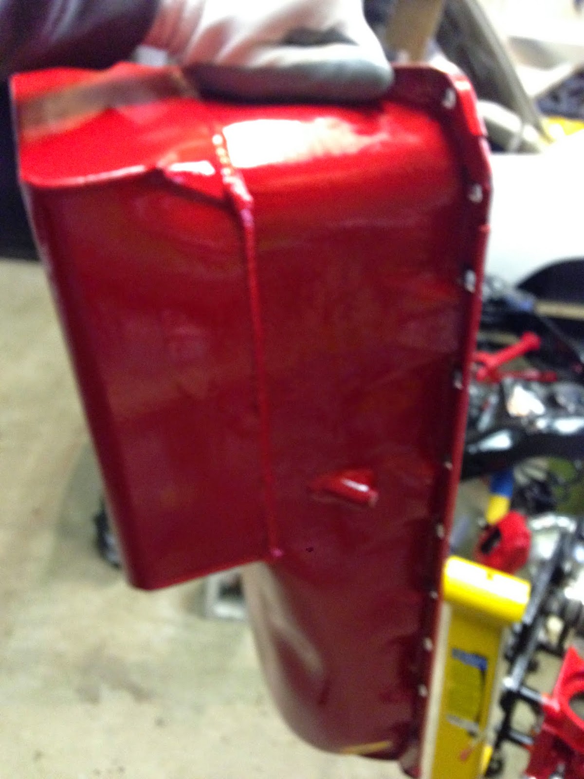
Here is a time lapse video I made of the final build of the engine. My next post I will describe in detail how everything went on the intial break in start. For now here is the video
https://www.youtube.com/watch?v=U47F7jKdHmc
Friday, August 21, 2015
Monday, May 18, 2015
Engine Build Final Assembly
I haven't posted on here in a awhile, so I thought I'd throw out a post just to give those following my blog a little update. It's not that I haven't been doing any work, I actually have been out in the garage a lot lately working on the final assembly of the 454. I am just going about the documenting of this stage a different way. I am putting together a time-lapse photography video of the complete final build. I won't be posting it until it is complete, so stay tuned. But for now here is a couple pictures of where I'm at now.
Sunday, January 25, 2015
Sidetracked Continued
 '
'
I was also done with all my pre-assembly checks for the engine. So in my spare time I've been disassembling it and storing the parts in preparation for the final block cleaning and assembly.
Here is my expert technician lending me a hand
Before the final block cleaning and assembly, I took this time to install a lifter valley screen kit that I purchased from Milodon. This kit is installed as insurance in case any valve train failures were ever to occur. The screens that are epoxied to the oil drain down holes would catch any small pieces preventing damage to the lower rotating assembly. It's not that I don't trust my work, I just thought for $30 why not? Looking back now I probably could have made the screens myself and just bought some epoxy, instead of buying the kit.
Below is a picture of the screens epoxied in. Not the prettiest work, but this won't be seen.
In the kit there is also a screen to install in the opening where the oil goes into the timing chain area. This screen was hammered in place using a hammer and socket.
I've also picked up a new water pump. I found it on Rockauto.com for $15. It's for a 1980 Suburban truck. It should do the job, if not I'm only out $15.
I also had a meeting with the guy who is going to be doing all the body and paint work for the Chevelle. We set a tentative date for next January. I can't wait!
That is it for now. I think next job for me will be to start installing brake lines and fuel lines on the Chevelle's frame. I am going to start final engine assembly when it gets a little nicer outside so I can roll it out into the driveway and wash it.
Friday, December 5, 2014
Engine Build Pre-Assembly (Oil Pump Fit and Clearance to Pan)
I am almost coming to the end of the pre-assembly stage of my engine build, there are just a few other things to do. With both heads on the block tightened down just snug (not torgued) I installed the intake manifold with just 4 bolts to make sure it lined up on the heads ok.
I'm really glad I went with the black powdercoated version on the intake manifold. I really like the look of the black on red, and it will go well with the black on red look of my chevelle when it's done.
I then test fitted the distributor in the block and tightened it down with it's hold down clamp, because next I will be turning the engine upside down.
With the engine upside down I put the oil pump driveshaft down into it's hole in the block.
The picture below shows the oil pump driveshaft in the block. Also I installed the oil pump stud in the block.
I then tightened the oil pump onto it's stud.
The oil pump driveshaft play is then measured. To do this, using my pinky finger I slid the driveshaft as far up as it would go. I then drew a line on the oil pump, where the two met. I then pushed the driveshaft down as far as it would go and made another line.
Below are the two lines that were made on the oil pump shaft. This indicates that there is some endplay with the driveshaft, which is good.
I next installed the oil pump pickup into it's hole in the oil pump. It is a press fit and had to be tapped down into the hole using a punch.
The oil pump and pickup that came in my kit had a locating tab on the pickup that set the pickup to it's desired depth within the kit's oil pan. I will be verifying the clearance between the pan and pickup just to be sure.
The bolt in the oil pump kit is removed and then reinstalled over the pickup locating tab.
Here is the oil pan
To check the clearance between the pan and the oil pickup, I once again pulled out some modeling clay. I placed a blob on top of the pickup.
The pan was then placed onto the block, which in turn squished the clay to the clearance. I then removed the pan again and using my calipers measured the thickness of the clay. I forgot to take a picture of this, but I measured the clearance to a little bit less then 3/8" which is good.
All my engine pre-assembly checks have now been completed. I am happy with all my measurements that I have taken. I now will start to dissassemble the engine in preparation for final assembly.
Thursday, December 4, 2014
Engine Build Pre-Assembly (Piston to Valve Clearance)
Piston to valve clearance is a very important measurement that must be performed in any engine build. In all my research I came across two different methods of doing this. The first is using a dial gauge set up on the valve spring retainer and checking at different intervals of crankshaft revolution how far the valve can be pushed down before contacting the piston (more on this farther down). The other method of checking is using clay, which I will explain. I did both checks, this is my first engine build so I figure better safe than sorry.
The degree wheel is used again for this check. I brought the piston to 20 degrees before top dead centre (BTDC) as my starting point.
I then pushed down on the lifter slowly watching the dial gauge until I felt the valve contact the piston. I recorded the reading from the gauge at this point. I then moved the crankshaft in the normal rotation (clockwise) to different degrees in the crankshaft rotation and did the same thing.
After I did the measurements for the intake valve I moved the setup over to the exhaust valve and did the same thing.
Below are the recordings that I got at each interval. It looks like the closest clearances seem to be about 8-10 degrees after top dead centre on the intake valve and 6-8 degrees before top dead centre. Minimum clearance on the intake valve should be 0.080" or more and for the exhaust side 0.100" or more. My numbers are well within safe limits.
Next I decided to see what clearance numbers I get using the clay method. I won't be needing to have the light weight checking springs on the number 1 valves anymore so I first swapped the regular springs back into the head.
Below I have my valve spring compressor set up.
The valve is compressed to insert the two valve retainers in
Below are the two valve spring retainers
Valve spring installed
To perform the clay method of checking piston to valve clearance the head gasket needs to be used also to get a accurate value.
A chunk of modeling clay was placed on the #1 piston, enough to cover the whole span of the piston where the intake and exhaust valves are.
The cylinder head was then placed on the block and just snugged down.
The valve train for the #1 cylinder are setup again. Once again using the lifters that I made into solid lifters. The engine was then turned over a few times, enough that the intake and exhaust valve open a couple times.
Everything is then taken off again. Below the intake and exhaust valve indentations in the clay can be seen.
Carefully using an x-acto knife I cut each indentation in half. I then used my calipers to measure each indentation at it's thinest points.
Sunday, November 9, 2014
Sidetracked
The engine build has been put on hold for the time being. Winter is coming here in Canada and I'm trying to get my garage in order before the snow hits. I thought I'd just let everyone that's following my blog know what I've been up to.
My garage isn't heated or insulated. After last years winter that seen temperatures dropping close to -40 I decided it needs to be heated if I want to get anything accomplished. I went over across the border to Menards and got a good deal on some R38 insulation and used this to insulate the ceiling. I also picked up a 50k btu Mr. Heater at Lowes. Hopefully it does the job.
Here is a picture of it hung on the ceiling. I just have to get the gas and electrical hooked up and the exhaust.
I also got an early christmas present. A new tool chest. I've been looking for awhile for a bigger tool chest to accomodate my ever growing tool collection. So I finally broke down and went and got the biggest chest combo Canadian Tire offered in their store. If it doesn't fit all my tools, then I think I need to get rid of some.
With alot of my garage time lately I've been transferring my tools into the new chest.
I'm still going to use my old tool boxes. I think I'm going to use them to hold chevelle/engine parts and stuff like that.
I'm hoping with all the newly aquired storage I can cut down on the clutter, which can be seen on my tool bench in the above picture. I know it's bad.....haha
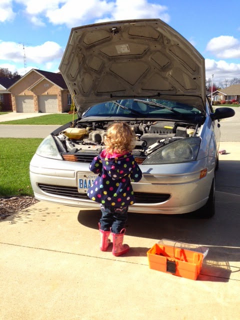
I've also been using some of my time to make repairs on our family vehicles and getting our house ready for the winter.
Here's my helper mechanic making some repairs to my Focus.
Anyways, that's what I've been up to lately. I will get back to the engine build soon. If anyone has any suggestions on some tool chest organization tips I would gladly take some. Just comment on this post.
Subscribe to:
Posts (Atom)


