Monday, June 23, 2014

Engine Build Pre-Assembly (crank straightness, crank measurements and main bearing oil clearances)

 
Before I put the engine together for the final assembly there are some critical measurements and clearance checks that need to be completed in any motor to ensure that this engine will have a long life.  In the next few entries I will be going through these checks and I will try and explain the best I can.
 
Here is the Crankshaft.  I cleaned it up with some brake cleaner.
 

The first thing that I checked is the straightness of the crankshaft.  To do this I installed the #1 and #5 main journal bearings with some lube, I then set the crankshaft into the block carefully (it's heavy!).  I then install the main caps on #1 and #5 and torqued them to spec.


To check the straightness of the crankshaft, I used my magnetic base with a dial indicator setup on the #3 journal.  I zeroed the dial and then rotated the crankshaft a few times and see if the dial reads anything.  I then moved the dial indicator to the front snout of the crankshaft did the same thing.  I then took the #5 main cap off and put the dial indicator on the rear main seal surface.  everything checked out perfect, which means the crankshaft is perfectly straight. 


Here is a picture of the main caps with their bearing halfs installed. 


I then installed the rest of the main bearings in the block.  I then lubed the bearings up, set the crank back into the block.  I installed all the main caps and torqued them to spec and then spun the crank by hand making sure it spun with ease.


Every time I torqued any bolts down I coated the threads and washer faces with ARP lube.  This is used provide accurate torque readings each time.


The main caps were then taken off and the crank was then removed again.  The lube on all the bearing surfaces was then all wiped clean and the main caps are reinstalled without the crankshaft and torqued to spec again.


I then took my 2"-3" micrometer and measured every journal on the crankshaft and recorded the readings I got.  These readings will be used later. 


The next check I did required using a dial bore gauge.  I had never used a dial bore gauge before, so it definitely took me a little while to get the hang of this tool.  I'm not going to go into much detail on how to use this tool, but if you are wondering how to use it I found a lot of helpful youtube videos on how to use one.  I was using it to check oil clearances.  so what I did was take each journal measurement from the crankshaft and set zero on the dial bore gauge to that measurement.  Then when I put the dial bore gauge into each main bore in the block and took the reading it read the difference between the crank and the block, giving me my oil clearances


I then repeated this for each main bore and recorded each reading


All the main oil clearances on #1-4 bores came in between .0025" - .0028" and the #5 bore came in at .0032".  It is normal for the #5 main oil clearance to run a little looser.  I would like to note that all these measurements I did were double and triple checked each time.  I am happy with all the measurements I got so far and are right on spec for my engine.


Just as a added insurance, I decided to check all the main oil clearances with Plastigauge.  Plastigauge is a little strip of plastic that is put on each crank journal, then the caps are torqued down on top of it.  When the caps are torqued down it squishes the plastic.  The caps are then removed and the squished plastic is then compared to a clearance chart, giving a clearance measurement.  This method is less accurate but still works.


The thin strip of plasticgauge is hard to see in the picture below unless you look closely


In the picture below, I am comparing the squished plastigauge to the comparison chart found on the plastigauge package.  All my plastigauge readings came in at around .002" give or take a bit.  So as this is a less accurate method of measuring clearances I am happy with those results.


In the picture below it shows my white board that I mounted to my garage wall.  I bought this from walmart and find it to be a great investment, it comes in very handy for recording all my results as I go.


Engine Build Pre-Assembly

I haven't posted on here in a few months.  My family life has become extremely busy these last few months with preparing for the birth of our second child, different odd jobs around the house,  a basement flood,  a few repairs to my Focus and then finally, the birth of our second little girl this month.  So my garage life has taken a bit of a hiatus up until about last week where I was able to sneak out there for a few hours each day while our 2 year old napped.  I have started to get my engine parts together and organized and have started performing some pre-assembly measurements and checks on the engine.

At one point I had decided that I was going to leave the building of my 454 big block build up to the machine shop that performed all the maching work to the block, but have actually decided recently that I am going to build it myself.  I have wanted to do an engine build myself ever since high school automotive class where we were given the oportunity to tear apart an engine and put it back together.  I keep on telling myself that you only live once so why not do the things I want to do.  With the amount of research and books that I've read so far on building engines I am fairly confident at this point in doing the job myself.  I will try and explain myself the best I can on here during the process.

The first thing I did before I even touched any of the engine parts was tidy up my garage.  It was a disaster!  so after a couple hours I had the garage to the point where it was tidier and I had a little more room to work on my benches.

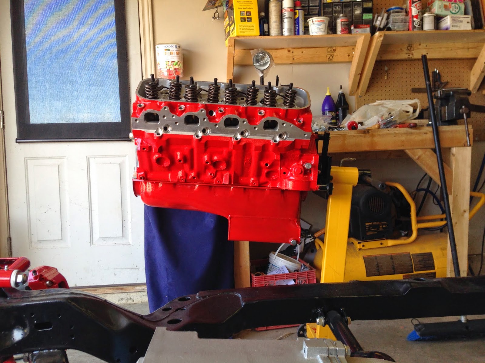
A couple years ago when I just had the engine block my plans for my chevelle were a little different.  I have since changed some details of my build.  I had originally painted the block Chevy orange.  I have now decided I want the block to match the colour of my brakes and suspension.  so after a few different paint colours I found a engine enamel in a red colour that is almost a perfect match.  It ended up being POR 15 engine enamel in "Ford Red", so I officially appologize to the die hard chevy people out there for using this "Ford" colour.  I have a Ford Focus and a Ford Escape out in the driveway so I have no problem with tossing a little Ford into the mix.

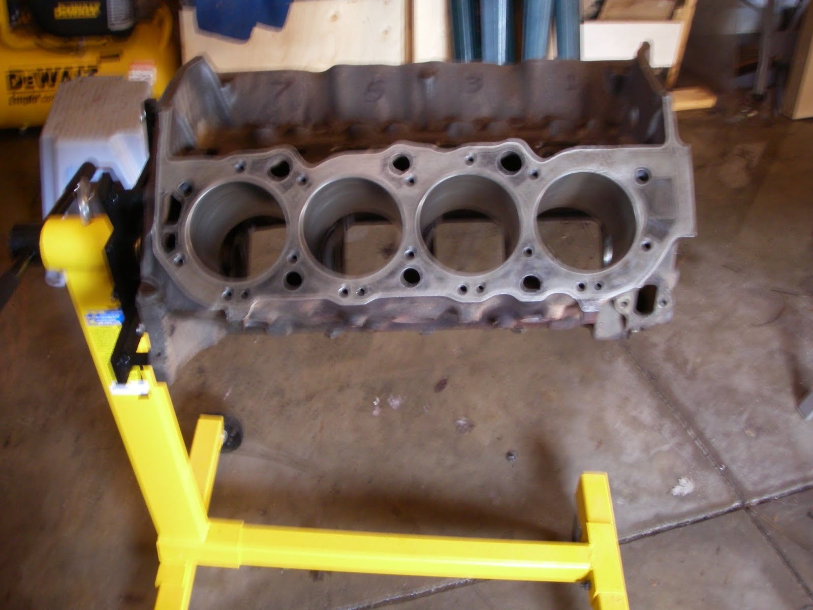
Here is the block before the Red


I sanded the whole block and oil pan with 300 grit sandpaper to help the new paint adhere better.  After I masked off everything I didn't want to be red, I started laying down some of the new colour.  I really like the POR 15 paints.  I could apply with a brush and it still drys perfectly smooth, and rock hard.


Some people may ask "why did you paint your aluminum heads!"  well I had seen this done while looking at other peoples builds and I liked the look..... so that's why.  I'm glad I did it because,  I'm very happy with how it turned out.


After I had let the parts dry I took it all back apart.    Next, I waited for a nice day, took everything out into the driveway and gave it all a thorough cleaning.  I used a mixture of laundry detergent and water and scrubbed everything with a variety of brushes.  I used a toilet brush to scrub the cylinder walls, don't worry it was brand new, it worked well.   I did all this cleaning as fast as I could while making sure to keep the block wet at all times because the freshly machined surfaces are VERY prone to rusting very fast.  Once the cleaning was complete I sprayed everything down with WD-40 while also using my air compressor to blowdry the block.  Once I was confident the block was dry I rubbed the cylinders down with ATF to keep them from rusting.  I covered the block up with a clear garbage bag.

Here is a picture of it all cleaned and sparkling.  Now I can start on the Pre-assembly measurements.


Tuesday, February 11, 2014

Engine Parts Continued

Today I picked up my package that I had ordered from Summit Racing.com.  Just like a kid on christmas morning I came home and opened everything up and took pictures. 

This is a set of Comp Cams aluminum 1.7 ratio roller rockers.


In the top box is a set of ARP cylinder head bolts specifically designed for my Edelbrock Performer RPM heads.  On the right is a rear main oil seal from Fel-Pro.  On the left is a cam bolt set and locking tab.  These bolts secure the timing gear to the camshaft.  I don't really get why these bolts weren't supplied with my cam.  I had to buy them separate.  The package on the bottom middle is the oil filter adapter.


These are the head gaskets I will be using from Fel-Pro.


Some of the last items were just some more tools.  A valve spring compressor tool - which I will be using to swap out the valve springs on my head (at the #1 cylinder) and replacing them with light weight checking springs (pictured in middle).  These light weight springs are used when taking some of the pre-assembly measurements (cam degreeing, piston to valve clearances, push rod length) before final assembly.  They are needed because I am using hydraulic lifters in my engine.  Hydraulic lifters, under normal engine running conditions, have a plunger inside them that is pressurized with motor oil.  Without the engine running when I am doing these checks the plunger will just collapse under the pressure of the normal springs.  That is why the light weight springs are swapped in place-  to allow me to turn the engine over by hand without the lifter plungers collapsing, providing me with accurate results.  I will go more into detail about this later.

Also below is a tapered piston ring compressor tool,  crankshaft turning socket and a pair of connecting rod bolt protectors.

The bottom picture is a degree wheel, used when degreeing the camshaft.


Sunday, February 9, 2014

Engine


I haven't posted on here for awhile because I haven't really done much out in the garage in the last few months, I have just been reading books on engine building and building up my parts inventory for my engine build. Well I can say now that I have almost all my parts for the engine.  I am just waiting on spring weather to start on the engine build.  My garage is not insulated (going to insulate it this year) so it is VERY cold.  I didn't think it would be a good idea to make measurements on the engine and parts in this cold weather as this can throw the accuracy of my tools and measurements off.

In this post I'll show some of parts that I will be using for the engine build.

Here is the block a few years ago when I bought it.  The only work that had been done to it was the cylinders were bored out to match the pistons that I purchased with the block.  The block was bored 0.030" over.  454 block bored 0.030" makes this a 460 cubic inch beast! 


I brought my block and rotating assembly into Atchison Machining in London, Ontario.  Here I had them look over everything and do whatever was needed to get it ready for assembly. The Block, Crank and Rods were all magnafluxed.  This checks for cracks/flaws, and everything checked out good.  The block was decked to clean up the mating surface between the block and heads.  The main journals were alignhoned to make sure they were perfectly straight.  The rotating assembly (Crank, Rods, Pistons, Flywheel, Balancer) were all balanced.  The crank was ground down .010" on the main journals and rod journals, to clean it up and get it in spec.    When I got it home I painted the block "Chevy Orange" with POR15 paint.  I am actually going to repaint this Red to match the Chevelle's suspension and brakes.


This is the Eagle forged crankshaft. The crankshaft being forged is a little overkill as this motor will never see the horsepower levels that justify using a forged crankshaft, but I purchased it used along with the rods, balancer, flywheel, bearings.  so it came with the package, and it just sounds cooler doesn't it?.....

All the journals were ground 0.010" to clean them up.


For the connecting rods I got my hands on some Eagle forged H beam rods.  These rods are the stock 454 length at 6.135".  They have a floating wrist pin, which means they aren't pressed onto the piston, but are held in place with spiral locks.
 
The Pistons were purchased along with the block because they were machined to match the bore in the block.  They are Keith Blacks 0.030" overbore hypereutectic aluminum pistons.  


For piston rings I got a set of "file to fit" speed pros.  I placed them in each cylinder one at a time and filed them to get a top ring gap of 0.028" and 2nd ring gap of 0.018"(I will double check these before final assembly), these were the gaps that were recommended to me from Keith Black.  Each set of rings were bagged and labelled for each specific cylinder.


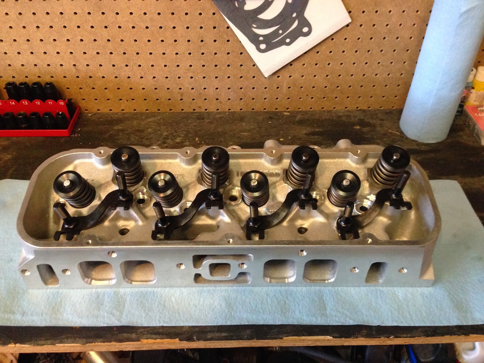
For cylinder heads I got a set of Edelbrock Performer RPM's.  They came preassembled with valvesprings, and 2.19" intake and 1.88" exhaust valves.  I actually ordered the wrong heads.  These heads were set up with valvesprings for a hydraulic flat tappet camshaft.   To fix this I sent the heads into the machine shop and they installed shims which brought the spring pressures into range for a hydraulic roller camshaft.  I'm very glad that I caught that mistake as that error could have caused major problems down the road. 


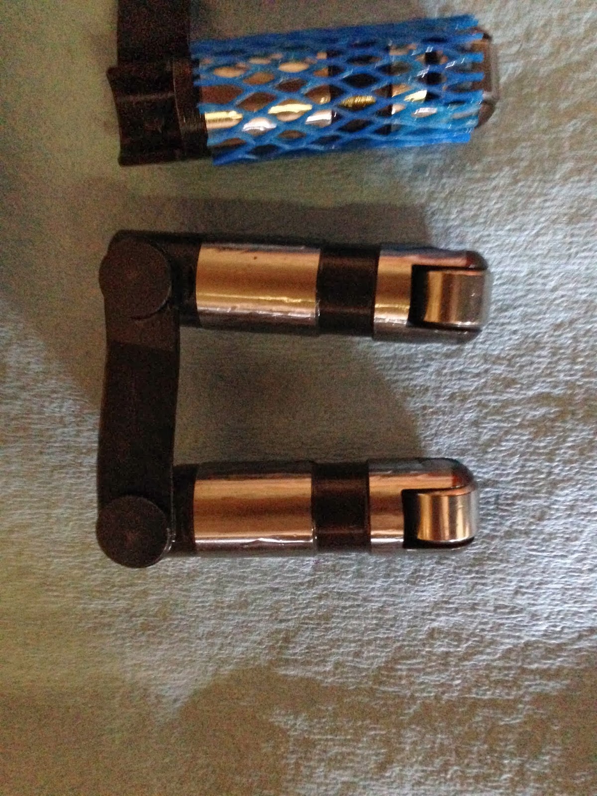
For camshaft I picked up Comp Cams XR294 hydraulic roller kit. This kit included cam, hydraulic roller lifters and double roller timing set. This cam will make plenty of power in this engine.


During the last few months I've also been building up my inventory of engine building tools.  I got myself a dial bore gauge, this will come in handy with measuring bores and clearances.  I got myself some micrometers.  I got myself a magnetic base with a dial gauge.  I also got myself a new tourque wrench.


 I also placed an order with Summit Racing for some more parts last night.  I will have another post when I get my package.